How to Build a “Podracer,” or Double Pulk Sled (Optimized for use with the PulseEKKO Pro GPR system with 100 MHz dipole antennas).
A pulk sled is a sled designed to be pulled by a skier or snowshoer carrying a decent amount of weight, such as firewood. It has a stiff set of reigns made from a material like PVC or wood that make it so that the sled doesn’t run into the back of your heels as you’re walking along in the forest. A good guide to building a standard pulk sled can be found at https://www.rei.com/blog/snowsports/diy-make-your-own-pulk-sled
We had to make a specialized double pulk sled to carry our geophysical equipment during field work. We were using a ground-penetrating radar (GPR) system with transmitting (Tx) and receiving (Rx) antennas that are required to be kept at a constant one meter spacing apart throughout data acquisition. We therefore attached two sleds together with a rigid frame to maintain that spacing. We dubbed the result the podracer, for its similarity to the hovercraft vehicles in Star Wars.
This document describes the construction of the podracer for those who may desire to recreate it for a similar geophysical system. Read the above link on building a standard pulk sled before continuing in this guide; we based the podracer on it.

Figure 1: Pulk sled, or podracer in stacked single sled mode for transporting equipment.
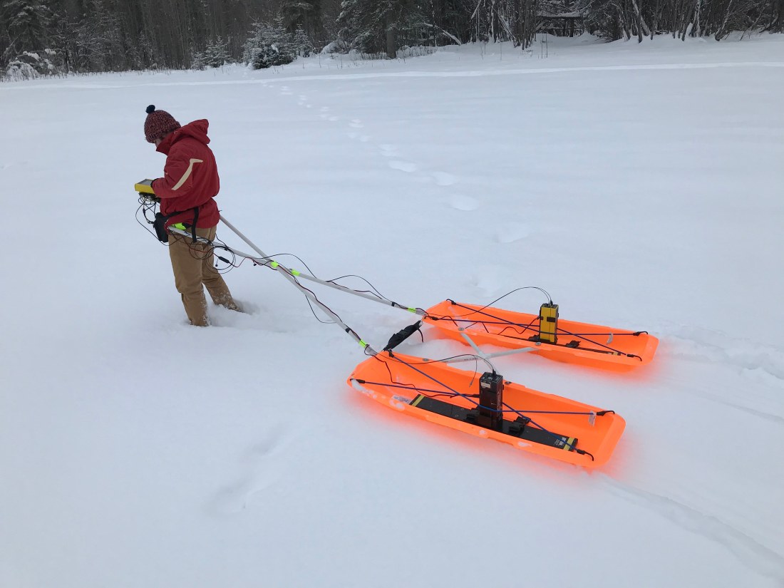

Figure 2: Use of podracer in double-sled mode for use with PulseEKKO Pro GPR system data acquisition.
Additional materials needed for the podracer are:
(For fastening the sleds together):
4-way cross PVC joint, ½”
4 pieces of ½” PVC pipe of length L_p (defined below)
Four additional ¼” x 2” adjustable clevis pins
Four additional key rings
Glue for PVC joint (not used on prototype, optional but recommended for future sled)
(For fastening in the PulseEKKO Tx & Rx):
Additional 10 ft of 2” Webbing
4 Additional 2” Plastic Buckles
Eight ¼” x ½” length hex bolt
Eight ¼” hex nut
Twelve 1/4” interior dimension wide washers
Four ~36” (or close to just less than sled length L) bungee cords
Directions:
- Follow directions found in REI guide for building single DIY Pulk Sled; do this for one set of harness poles and both sleds. The podracer is designed so that it can be operated in single sled mode with sleds stacked and harness poles threaded through both sleds’ eyelets; when the survey area is reached the sleds can be unstacked and the podracer assembled in its full form.
- Note: select two identical sleds with a flat bed length > 1 m such that it can accommodate the PulseEKKO Pro’s 100 MHz antennas

Figure 3: Podracer in the process of assembly
- Build PVC Cross connection between sleds
- The goal here is to connect the sleds with a rigid PVC cross piece such that the centers of the sleds are spaced 1 m apart, optimal for the 100 MHz antennas.
- Cut 4 pieces of ½” PVC pipe to L_p = sqrt(2)/2 (100 cm – W_sled), where W_sled is the width of the sled in cm.
- Connect the 4 PVC pieces to the cross joint, using glue if desired.
- Drill 3/8” holes in the ends of the PVC pieces, perpendicular to the plane of the cross
- Drill two 3/8” holes in the inside edges of each of the sleds, spaced at (100 cm – W_sled) distance apart and at identical locations on each sled—these should match to two holes of the PVC cross.
- Note: we found that two pre-existing holes in the sleds purchased for the podracer prototype corresponded exactly to this distance so were able to use those instead of drilling our own.
- The PVC cross can now be connected to the sleds by use of the clevis pins. I recommend inserting the pins from the bottom through the PVC first then the sled, allowing easy accessibility when inserting the key ring to lock the PVC cross in place.
- You now have the podracer connected! The clevis pin/PVC cross connection can easily be attached and removed to switch between single-sled and double-sled modes. The harness poles in double-sled mode are attached to the eyelets on the inside edge of each sled and should operate in a similar fashion to single sled mode (see pictures).
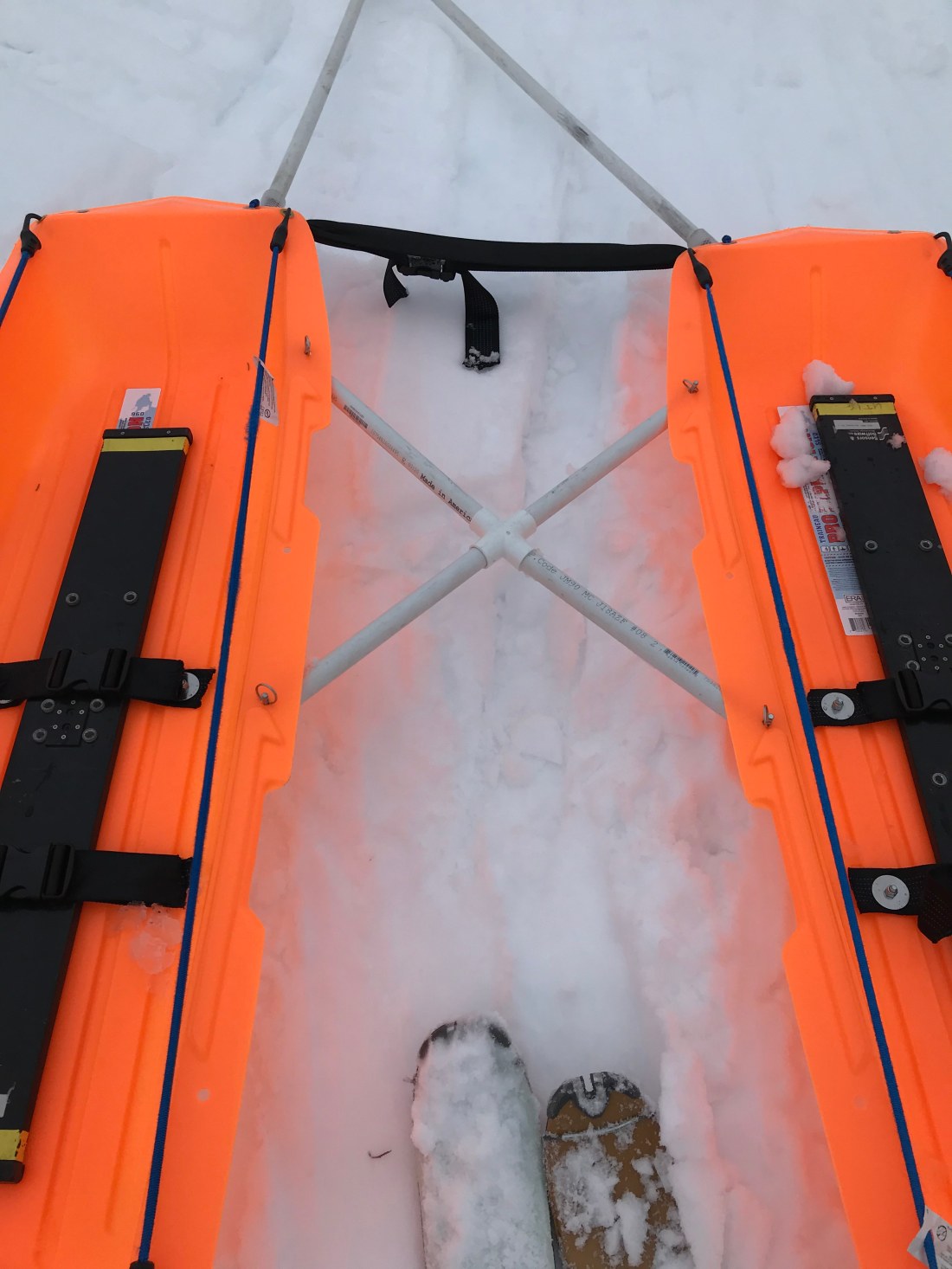
Figure 4: Context view of PVC cross connection.

Figure 5: Detail view of clevis pin connection between PVC cross and sled.

Figure 6: Attachment between harness poles and podracer. Connection is the same as for single sled (described on REI page), but is connected to inside corners of each sled. Note in the background one of the PVC pieces is missing from the cross-piece, having fallen out after a particularly rough trip—this was an unusual occurrence but happened twice during our fieldtrip. For this reason we recommend future iterations use a glue between the PVC pieces and the cross joint.
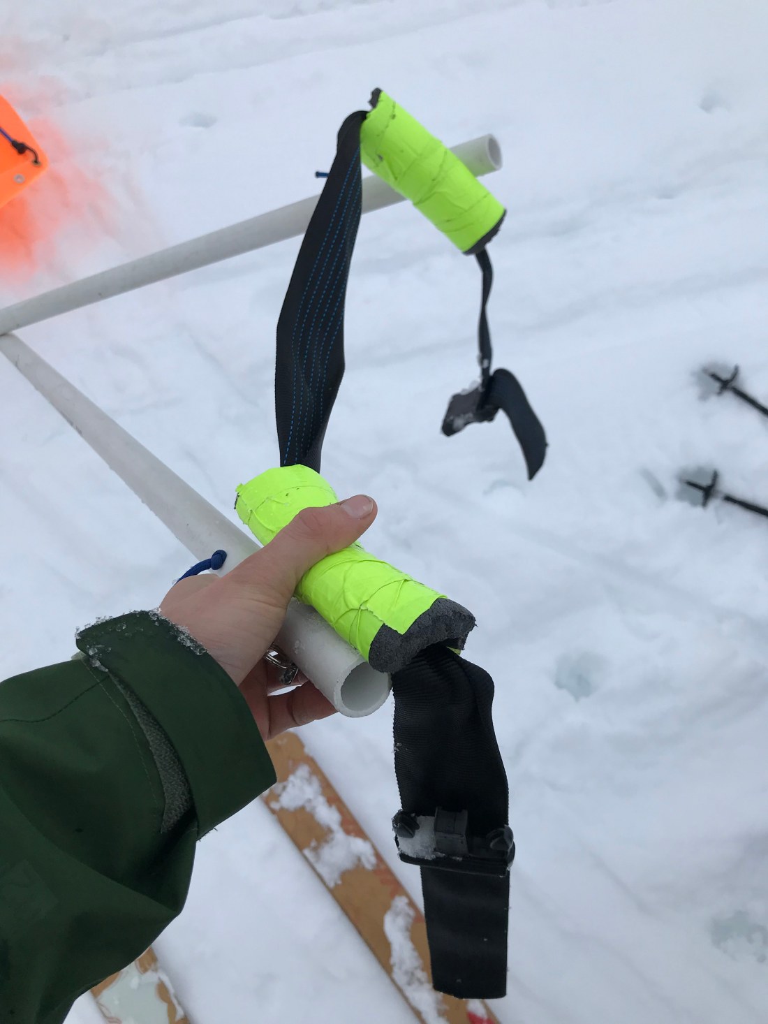
Figure 7: Our homemade harness. We recommend that climbing harnesses, if available, are used and an appropriate connection made to the sled’s PVC reigns; this may lead to more comfortable operation and greater ease with switching sled operators.
- Build strap assembly to secure PulseEKKO Pro 100 MHz Antennas
- Drill four 3/8” holes in the bed of each sled, forming a rectangle centered roughly on the center of the sled bed with a length parallel to the sled length of about 20-25 cm and a width similarly of ~20cm. It is critical that the holes are drilled in the spaces between the sled runners, so that the bolts when installed do not create excessive friction when operating the sled. It is also critical that the holes are drilled in the same locations on both sleds so that the antennas are centered in the same location on each sled.
- Cut 8 segments of 2” webbing to ~30 cm length and burn the edges to prevent fraying. Make a hole in the center of each piece of webbing about 3 cm from one of the ends.
- Insert ¼” bolt through the bottom of each hole drilled in sled bed. Place webbing piece on upper side so that bolt is inserted into webbing hole. Place washer and nut on bolt and tighten.
- Attach 2” buckles to webbing pieces bolted into sled; matching buckle pieces should between webbing on either side of sled so that when buckled they make connections transverse to the sled running direction. When using the PulseEKKO Pro the 100 MHz antennas are placed in the bed and the buckles tightened down on the antennas with the Tx and Rx modules between buckles (see photos).
- Attach 36” bungee cords so that each runs the length of the sled on its side from front to back. When the Tx and Rx modules are placed on the antennas in the sled the bungee cords are tensioned against the opposite side of the module from the side of the sled they are attached to, creating equal and opposing forces to stabilize the top-heavy Tx & Rx modules.
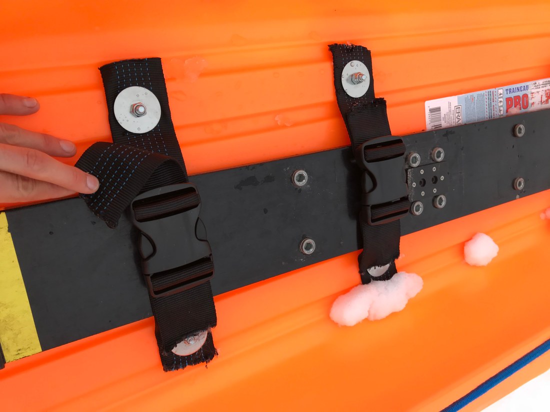
Figure 8: Detail of completed webbing buckle assembly bolted to sled bed for securing PulseEKKO Pro Antennas.
- When running the PulseEKKO Pro on the sleds, use medium-length fiber optic cables between the Tx/Rx modules and the control console. Tape them along the harness PVC poles so that the operator of the podracer can carry the console with him/her and there is enough slack on both ends that no tension is created as the podracer is operated.
- Enjoy your podracer!
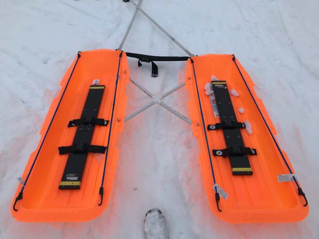
Figure 9: Full view of podracer with PVC cross connectors, antenna straps, and bungee cords in rest position. Tx and Rx modules are not in place.
Additional Notes on the Podracer:
- We used 2 Paris Company Expedition Sleds for our prototype and they worked perfectly: https://www.rei.com/product/609482/paris-company-expedition-sled
- Sled width was 50 cm, leading to sled spacing of 50 cm and PVC pipe length of 35.4 cm or 13.9 in. We rounded up to 36 cm.
- Eyelets 1 & 3 on the sides of the sleds were spaced at 51 cm; we opportunistically used these to connect our PVC cross connection.
- The homemade harness system built from REI’s guide was sometimes uncomfortable to use and unwieldy to put on/take off. We recommend future iterations experiment with integrating climbing harnesses that can easily be attached/removed from the assembly.
- The sled preformed very well on flat to gently sloping (up to ~15 degree) and moderately rough surfaces but preformed poorly on steep slopes (> ~15 degree) or surfaces rough enough to catch/stop the sled. When sufficiently steep slopes are attempted the tension on the PVC reigns becomes great enough to raise the center of the podracer causing the sleds to rotate bottom inwards—this is undesirable for data acquisition.

Figure 10: Full podracer assembly with Tx & Rx modules in place. Antennas are strapped down and modules are stabilized by tensioned bungee cords. Fiber optic cables are seen connected to modules and taped to/routed up the PVC reigns. Sleds are filled with snow after a steep and rough GPR transect.
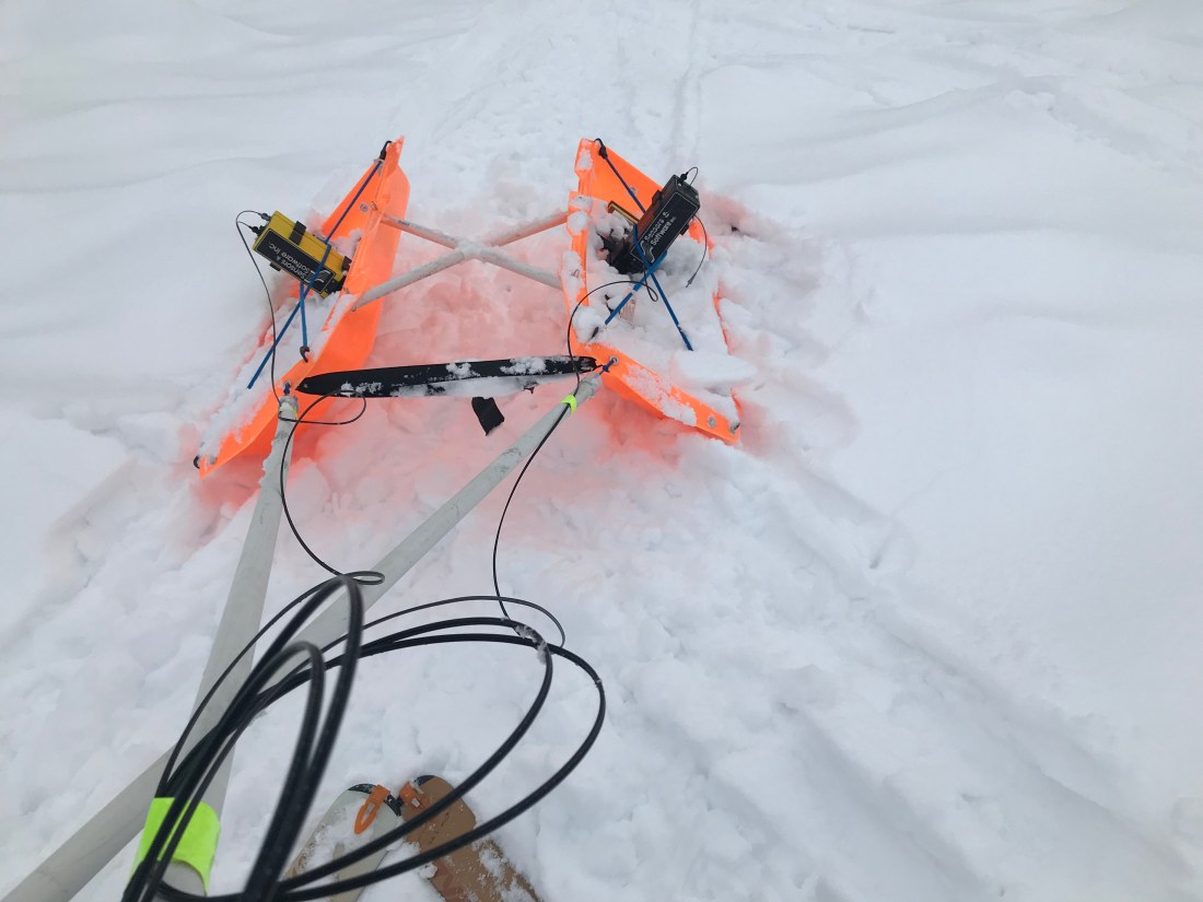
Figure 11: Podracer operation on steep (~20 degree) slope. High tension on PVC reigns is causing undesirable rotation of sleds. From this vantage point of the sled driver one can also see the routing of the fiber optic cables; excess cable is coiled and taped to the PVC pipe near the sled operator.
